Solar modules easily moved


Solar modules easily moved
Delivery period: August 2009
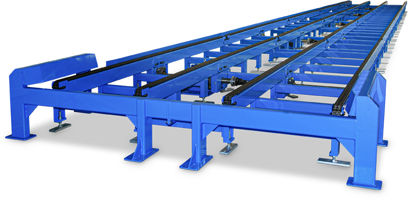
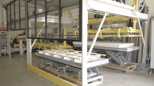
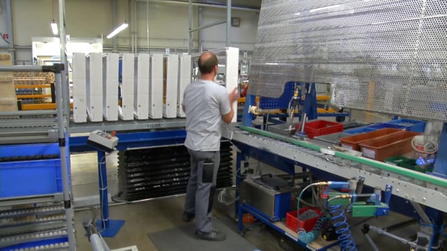
Sunfilm AG, a major manufacturer of thin-film solar modules based in Großröhrsdorf, Germany, commissioned an ALFOTEC conveyor system in November 2009, which temporarily stores the front and back glass of solar modules and provides them to production just-in-time. The system designed by Alfotec GmbH, Wermelskirchen – already the second system of this kind delivered to Sunfilm – consists essentially of two parallel four-strand chain conveyor systems. Self-supporting load carriers serve as carrier elements for the front and back glass of the solar modules, which ensure safe transport. Each of the 2,850 mm x 900 mm x 2,900 mm large load carriers has a total carrying capacity of 4,400 kg.
By loading the video, you accept Vimeo's privacy policy.
Learn more
Clients
Features
- Conveying Elements: Strand conveyor
- Convey Goods: Steel frames for flat glass panels - 4
400 kg (total load per element 22
000 kg max.) - Industry: Manufacturer of solar modules
History of the material to be conveyed
Coming from the goods receiving area, the filled load carriers are placed on one of the two conveyors by a reach truck. In order to ensure that the system is ready for operation and that no persons are present, the system is released beforehand by the forklift driver via a radio remote control. The correct depositing position for a load carrier is indicated to the forklift driver via light barriers and light scanners or by a green signal light. If the first load carrier is correctly positioned, it is continued over a length of about 1,000 mm. The second load carrier is then placed on top and pre-cycled.
This is repeated until a block consisting of five charge carriers is complete. This block is now transported – controlled by the mobile remote control of the forklift driver – to the end of the conveyor section or to the last free conveyor element. There the load carriers are removed by reach trucks and transported to the assembly stations for further processing. Here too, a traffic light signals whether the load carrier to be removed is correctly positioned.
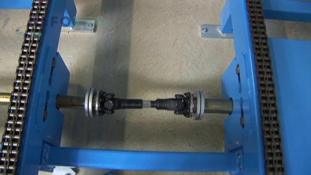
The entire plant, which is about 26 m long and about 6 m wide, is based on 11 standard chain conveyors of the KF series from the Alfotec delivery program. Since five load carriers arranged one behind the other result in a total load of 22,000 kg per conveyor, the load-bearing and drive elements are designed to be correspondingly robust and resilient. Not only are the load carriers each supported by four heavy-duty 1-inch duplex chains, but the drives of each conveyor system are also correspondingly powerful at 7.5 kW.
The control system, also supplied by Alfotec, includes all necessary control and function-relevant elements, wired up to the terminal strip. For this purpose, covered steel cable ducts with cable protection were installed on the hall floor in the area of the conveyor system. As safety measures, the entrance and exit areas, among other things, were each provided with impact protection for the forklift trucks. In addition, the entire facility is secured against unauthorized access with a protective fence or light grids.
Funding procedure
The block accumulation takes place with 5 racks each (one block). The first frame is placed on the chain conveyor and then conveyed one cycle (approx. 1,000 mm). The 2nd frame is put on and pre-cycled, this process is repeated until the 5th frame (block) is reached. If a block is complete, it is conveyed to the end of the line or to the last free conveyor element. A 4-strand chain conveyor with 1 inch duplex chain is used for conveying. The chain conveyors are designed for the operation of transport racks.
You can see further details in the video further up on this page.
Scope of delivery
- Adaptation of the software and extension of the user interface of the plant control
- Installation detection by means of light sensor and green signal lamp
- Ram protection with separate recesses for the forklift forks in the feeding area
- All cable ducts with covers
Remote controls (2x transmitter ORBIT, 1x receiver FSE508) from HBC Radiomatic GmbH are used.
More impressions


Fully automated palletizing
Fully automated palletizing
Delivery period: October 2013
The task The challenges The Solution
A company in the field of interior fittings, facade construction and insulation technology commissioned us to build a conveyor system. This was to palletise 6,000 mm long fibreboards, which were sawn into smaller pieces, on a special wooden pallet to save as much space as possible.
The conveying process in the video
By loading the video, you accept Vimeo's privacy policy.
Learn more
Features
- Conveying Elements: Roller conveyor
Strand conveyor
Converter and change of direction
Storage techniques - Convey Goods: Plaster Phase Plate Stack - 400 kg
Special wooden pallets - empty - Industry: Interior fittings
facade construction
insulation technology
The conveying process in detail
As the stacks have to be quickly lifted out, turned (max. 24 sec. / 2 stacks) and set down, a turnstile with Maltese cross gear was used. This is because it can turn 90° very quickly and precisely, start and brake gently and position the piles exactly on the pallet..

1. Two stacks of fibreboards move crosswise from a saw (not shown) to the feeding station.

2. A turnstile between the rollers lifts the stacks and turns them by 90°.

3. Then a stack is lifted again on the next roller conveyor and moved by a transverse shift. This separates the stacks.

4. At the end of the roller conveyor line the stacks are gripped and palletized. Important: Only one pallet at a time is fully stacked at a time!

5. The following procedure is provided so that the stacking process is not interrupted.
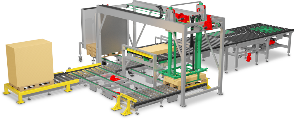
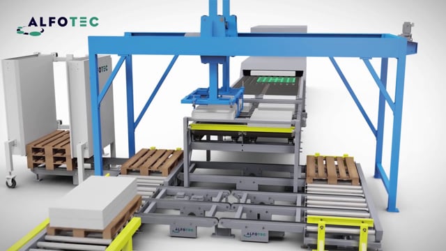
When stacking area 1 (following SP1) is full (the case in Fig. 5), the gantry system (PS) changes to SP2 with the stacking process on the empty pallet. The full pallet on SP1 moves to the delivery place (following AP), where it waits to be picked by a forklift truck. Then two pallets from the pallet dispenser move to SP1 and the reserve storage area (subsequently RP).
When the pallet on SP2 is full, the PS changes to the empty pallet on SP 1 and the full pallet on SP2 moves to the AP. The empty pallet on the RP now moves to SP2. When SP1 is full, the process starts again from the beginning.
Update
Expansion stage II
The customer was so satisfied that – after having invested about € 250,000 in this project – he extended the conveyor system only nine months after commissioning. The reason for this was that after the small-format gypsum fibre boards, the company now wanted to fully automate the palletising of large formats – with one and the same system. The ALFOTEC solution: We supplemented it with two gantry systems.
Grippers equipped with suction cups lift the boards (which are located on the roller conveyor already existing since expansion stage I) at an angle in order to release the vacuum between the boards lying flat. They then lift the panels vertically and transport them horizontally to the newly added lifting table opposite. A special wooden pallet is positioned on top of this, on which the panels are stacked with a tolerance of 0.1 mm up to the desired filling height or number of pieces. As you can see in the video, modern barrier techniques such as lifting gates and barriers ensure the safety of the employees.
With the expansion stage II, several goals were successfully implemented: The full automation of the palletizing, which was previously carried out manually in 3-shift operation, saves enormous personnel costs – with a noticeably higher capacity. In addition, the stacking quality has been significantly improved and is now – as desired – reproducible.
Technical details
1. Conveyed goods
- The following goods are conveyed in front of and inside the palletizing portal system: fibreboard stacks, weight: 400 kg / pallet
- The following goods are conveyed behind the palletizer-portal system: special wooden pallets, empty from the pallet dispenser, weight: 30 kg / piece
2. Scope of supply and services
- Conveyor system
- Palletizing portal system
- Chain conveyor with pneumatic stroke
- Chain ejector with pneumatic stroke
- Roller conveyor AU120
- Width-adjustable pallet dispenser
- Control with SPS control and frequency converter
- Assembly incl. commissioning and acceptance
- Safety fences, emergency stop, electrically locked access door and a safety light grid Multingsystem at the pallet exit
By loading the video, you accept Vimeo's privacy policy.
Learn more
Heavy duty chain conveyor
Heavy duty chain conveyor
Delivery period: March 2012
The client: MFL – Maschinenfabrik Liezen und Gießerei
The internationally operating MFL – Maschinenfabrik Liezen und Gießerei Ges.m.b.H. – is specialized in engineering, design and manufacturing of complex machines and plants. Special components and assemblies as well as steel castings complete the service portfolio. MFL was founded over 70 years ago at the Liezen site in Styria. Today the company employs almost 1,000 people. Under the motto “Perfection in all Areas” it offers its customers a perfect foundation for reliable engineering, customized production and precise project implementation.
The task
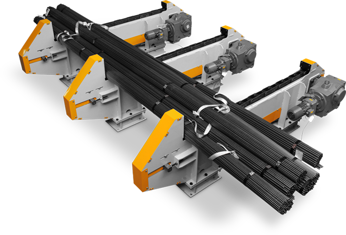
MFL commissioned us to build a free-standing heavy-duty chain conveyor. This was to transport various solid steel profiles with different lengths and cross-sections. And thus create a larger stock of material for the downstream saw. At the same time operating personnel was to be saved and personnel costs reduced.
The challenge was there:
- to consider that the task should be carried out by crane or manually
- to integrate the new solution into the existing acceptance facility
- to develop a weatherproof solution for outdoor operational areas, which is reliable even at temperatures of -10 to +35 °C and a humidity of max. 95%.
- to design the conveyor system for a total load of up to 34,000 kg
Clients
Features
- Conveying Elements: Strand conveyor
- Convey Goods: Round and square solid steel profiles
- Industry: Mechanical engineering
The solution – the conveying process
The heavy-duty chain conveyor is integrated in the infeed of a sawing line, with which heavy solid steel profiles are cut individually. As part of an automatic sawing line, it is also intended to serve as a storage magazine.

1. The raw material is manually deposited on the chain conveyor in bundles of four pieces each. The shocks to the strand chains during loading are reduced by installing rubber damping mats between the chain conveyor superstructure and substructure.

2. The chain conveyor transports the material to the end stop and remains in operation until at least two of five integrated sensors respond and trigger the message “Material aligned to stop”.

3. As the material is not parallel to the stops due to manual loading, increased wear between material and chain can occur during the alignment process. For this reason we decided to use a very robust conveyor chain type FVT 250 with pitch 160 mm.

4. After alignment at the end stop, the chain conveyor is switched off and one profile at a time is lifted above the material stop by the existing transfer device, deposited on a roller conveyor and transported to the saw.

5. Now the chain conveyor can transport the next profile to the end stop and remains in operation until at least two sensors respond again and trigger the message “Material aligned with material stop”.
Technical details for the heavy duty chain conveyo
1. Goods conveyed
- The following goods are transported: Round and square solid steel sections with different lengths (2,500 – 13,000 mm), cross-sections (60 – 250 mm) with a bar weight of max. 6,500 kg/each
2. Scope of supply and services
- Conveyor system
- Project planning, production, delivery
- 5 Chain conveyor

Conveying technology for pallets
Conveying technology for pallets
Delivery period: January 2012
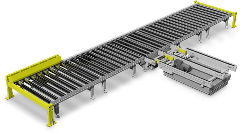
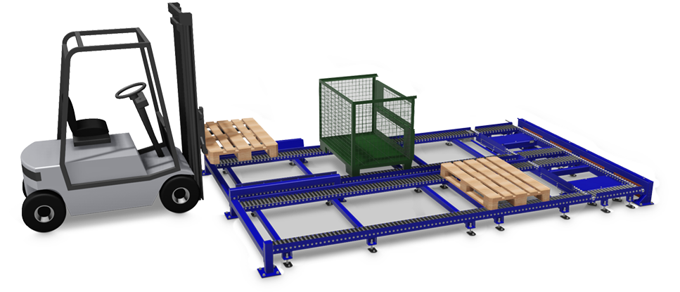
Conveying technology for pallets > 1.000 kg
In addition to precisely designed conveyor systems, we offer integrated control systems, on-site installation, protective enclosures and much more.


Merkmale
- Conveying Elements: Roller conveyor
Converter and change of direction
Lift table - Convey Goods: Euro pallets 1.500 kg
- Industry: Mechanical engineering

Feeding stations with rams protect the conveyor from the approaching forklift truck and help to place the pallet straight for further transport. Centering devices can also be executed on both sides and automatically.

Chain diverters lift the pallet and convey it to a line branching off at right angles. To lift the integrated chain conveyor, an eccentric lifter, lifting beam or lifting cylinder is used, depending on the requirements of lifting cycles and load capacity.

For easy loading and unloading, the pallet is brought to an ergonomic height. For this purpose, electro-hydraulic scissor lifts can be integrated into the conveyor line. For a safe transfer from the ejector to the lifting table, the chain drives are hinged.

After loading or unloading on the lifting table, the pallet returns to the discharge area. As soon as the pallet is back above the roller conveyor, the chain ejector lowers and places the pallet on the roller conveyor.
Afterwards, a buffer space enables the intermediate storage of a pallet. In this way, removal by forklift trucks and subsequent processes can be made more efficient. As each conveyor element has its own motor, they can be controlled separately.

The separate collection point is also equipped with a pile driver. Here, a horizontal cross strut prevents the forklift truck from damaging the support rollers of the roller conveyor by forks that are driven in too low.
Assembly line for VELUX
Assembly line for VELUX
Delivery period: August 2013
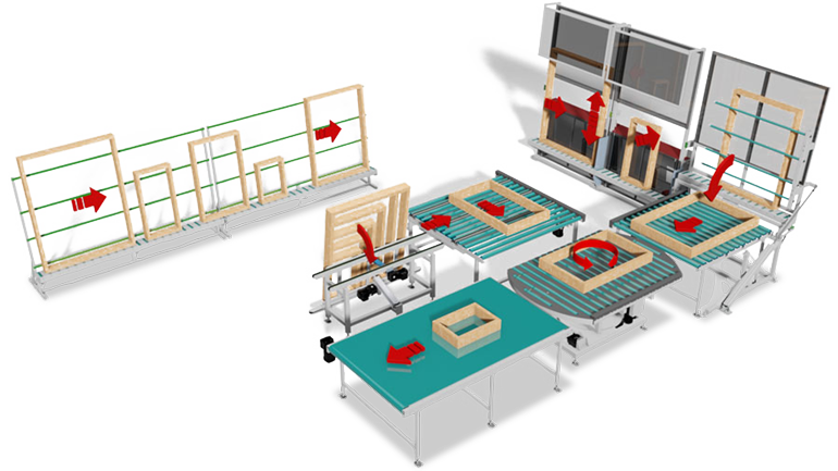
The client: SIG Sonneborn – VELUX Customer requirement – Ergonomically designed production line for the most automated possible assembly of window frames of various dimensions The customer’s task included challenges both with regard to the construction of the conveyor line itself and the commissioning. Working on the assembly line should not only meet ergonomic requirements, but also offer largely automated processes for standard dimensions of max. 2,000 x 1,600 mm (LxW) as well as all the necessary manual procedures for the assembly of individual and special frames. In addition, the workpieces should be tilted, turned and positioned exactly as required. The latter also referred to the transfer point to the continuing production line. The new assembly line was to be integrated into the existing conveyor system. After an extremely short delivery time of eight weeks, all installation and docking measures had to be carried out outside of operating hours in order not to impair the client’s production flow.
The “SIG Sonneborn Bauzubehör Industriegesellschaft mbH” manufactures the high-quality VELUX roof windows on a total area of approx. 170,000 sqm with a very modern machine park. As the German production company of the VELUX Group we have made an excellent name for ourselves. We secure long-term success with exemplary production technology, high productivity and constant quality improvement.
By loading the video, you accept Vimeo's privacy policy.
Learn more
Clients
Features
- Conveying Elements: Roller conveyor
Strand conveyor
Belt conveyor
Converter and change of direction - Convey Goods: Window frame with max. 15 kg
- Industry: Building accessories
Our solution
Two feeding stations and precise merging before transfer to another production line. The window frames in (different) standard dimensions are transported to the next work step via a buffer roller conveyor.


There the work surface is automatically adjusted to the correct height by means of servo motors. A drilling device attached to the rear of the unit drills the pre-set holes and milled out areas.

Afterwards the processed frames are carefully tilted into the horizontal position with the help of a pneumatic cylinder and transported on a driven roller conveyor in this position. A belt conveyor moves the frames to the removal point.

A second feeding station is used for manual processing of single frames and those with special dimensions.

After assembly, a pneumatically driven tilting station ensures gentle preparation for further horizontal transport via a roller conveyor with chain diverter. Below the belt conveyor in front of the unloading station is a driven turning station which can realign the manually mounted frames by up to 270° in the horizontal direction in order to prepare them in the correct position at the unloading station for removal.
The drives are controlled by PLC systems and frequency converters. Of course, our installation also includes all relevant safety devices, such as emergency stop switches and safety fences. As usual, our experienced specialists succeeded in putting the new assembly line into trouble-free operation within the agreed period and had it accepted by the customer.
Forklift truck on 8 t lifting table
Forklift truck on 8 t lifting table
Delivery period: September 2014
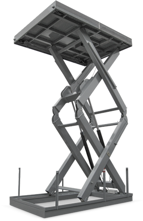
Die KSM Castings Group Requirement: Transport of castings between two floor levels Technical details: Vertical double scissor lift table according to DIN EN 1570
The KSM Castings Group is an international development partner and producer of light metal castings for the automotive industry.
At the Radevormwald plant of KSM Castings Group GmbH, parts were to be transported between the “casting production” and “casting machining” floors. What was unusual about this was that the material to be transported did not consist solely of the castings, but had to include an entire forklift weighing several tons, including lattice boxes and pallets.
| Platform length: | 4.000 mm |
| Platform width: | 3.000 mm |
| Resilience: | 8.000 kg |
| Overall height: | 1.300 mm |
| Lift: | 5.350 mm |
| Lift time: | ca. 98 sek |
| Performance: | 2 x 4,6 KW |
| Operating voltage: | 3 x 400 / 50 V/Hz |
| Valve voltage: | 24 VAC |
Clients
Features
- Conveying Elements: Lift table
- Convey Goods: Individual castings on pallets
lattice boxes
forklift - Industry: Metal / Automotive
Solution: Forklift truck on 8 t lifting table as conveyed material
The two production levels, 5.35 m apart, were connected by a specially secured shaft. A lifting table now conveys the forklift truck, including pallets and boxes containing cast products made of light metal for the automotive industry, from floor to floor.
This results in a total load of around 5 to 6 tonnes per transport. For the forklift truck, an additional point load had to be taken into account due to the four wheels and, in the case of the pallet cage, due to the four L-shaped feet, while the pallets have evenly distributed loads. This special load required a reinforced design of the platform. In some cases, the goods to be conveyed are not positioned over the entire surface of the platform, but only on one part. Therefore, after consulting ALFOTEC, KSM decided to use a robust lift table for 8 t conveyed material, which forgives unbalanced loads.


Security measures
Hazard protection also played a major role in the planning of the shaft. ALFOTEC used a shaft door on the ground floor for this purpose and installed a four-sided machine safety guard with double door on the upper floor. The doors are equipped with safety latches which were integrated into the lift table control. This means that the respective door can only be opened when the platform has reached the corresponding floor. Four electro-hydraulic locking bolts are used to secure the platform against lowering and they enter two shaft walls.
During assembly, the 6.3 t lift table was brought in by crane through the roof of the hall. The machine guards were installed immediately to eliminate the risk of falling right from the start. The lifting table was then lowered into the shaft with the hall crane with millimetre precision and secured to the floor. Power connection and integration of the door interlocks were the next steps. Finally, the ALFOTEC fitters adjusted the electro-hydraulic locking bolts.
More impressions


Successfully bolted to the workflow
Successfully bolted to the workflow
Delivery period: May 2014
Industrial washing plant intelligently equipped from 6 m depth
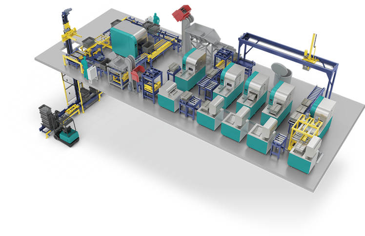
Screws go into a “washing machine” – that sounds unspectacular and almost trivial even in the context of an industrial company. But the many process details at the screw manufacturer make you sit up and take notice: Between the various production phases, high-quality screws and their steel transport boxes are repeatedly cleaned and dried in five washing machines and five dryers. Downtimes? Of course, these are best avoided altogether. Due to possible urgent batches even at high throughput rates, the SAP-controlled processes of the conveyor system are particularly flexible and efficient.

By loading the video, you accept YouTube's privacy policy.
Learn more
Features
- Conveying Elements: Roller conveyor
Strand conveyor
Converter and change of direction
Storage techniques
Lift table - Convey Goods: Empty and filled screw boxes
- Industry: Metal industry and processing
From the basement 6 m high to the car wash
Steel boxes full of screws weighing up to 500 kg are transported from the production area in the basement to the so-called FlexShuttle by forklift. Four transport boxes weighing up to 2 t together and stacked on top of each other are loaded onto the FlexShuttle by the forklift. In the interaction of FlexShuttle and lifter of the conveyor technology specialist ALFOTEC, the stack of boxes with the screws to be cleaned is destacked, separated and moved up to the ground floor, box by box.
The FlexShuttle consists of two mirror-inverted C-profiles. Inside, a carriage runs, which is pulled back and forth by means of a servo motor on a toothed belt in a precise position. Since the FlexShuttle can approach each individual box and close gaps, there is no loss of time and the available space is used quickly and to the maximum. When the lift reaches the ground floor, which is 6 m higher, it sets the box down: A roller conveyor mounted on a revolving platform swivels under the box, picks it up and swivels it through 90 degrees again to bring the transport box into the conveyor section of the car wash.
Five washing machines and dryers
Prior to the washing process, an employee transfers the box data to the SAP system by hand scanner, thus providing an overview of the production throughput. The scanning process also records which washing program is started. The system has been programmed intelligently and flexibly enough to control a total of five washing machines and five dryers, if necessary with express batches.


No “dead” places
Via the heart of the system, a traversing carriage, wash crates are intelligently transported through the conveyor system square to buffer space, lid stations, feed roller conveyors, washing and drying stations. The trolley is controlled in such a way that no “dead” spaces are created by prioritised buffering. The boxes are automatically tilted, thus being emptied and transported further, while the bundles of screws fall onto a vibrating plate and a rake separates them. It is not possible to wash the screws in the transport boxes, because they are not perforated, have no lid, are also dirty and are therefore separated from the screws before the washing process.
Cleaning of the wash boxes and their contents
Via the heart of the system, a traversing carriage, wash crates are intelligently transported through the conveyor system square to buffer space, lid stations, feed roller conveyors, washing and drying stations. The trolley is controlled in such a way that no “dead” spaces are created by prioritised buffering. The boxes are automatically tilted, thus being emptied and transported further, while the bundles of screws fall onto a vibrating plate and a rake separates them. It is not possible to wash the screws in the transport boxes, because they are not perforated, have no lid, are also dirty and are therefore separated from the screws before the washing process.

High safety standard
Der Schraubenhersteller setzt auf einen hohen Sicherheitsstandard: Lift, FlexShuttle und das Waschanlagen-Karree sind durch Schutzzäune eingehaust. The screw manufacturer relies on a high safety standard: Lift, FlexShuttle and the washing bay are enclosed by protective fences. In addition, a light barrier brings the conveyor to a standstill, for example when a forklift truck in the basement drives into the lift with the FlexShuttle for loading or unloading, or on the upper level the boxes are scanned before the washing process.
Unusually high requirements
All those involved know that the requirements are unusually high because many different processes run in parallel and, due to the integration into a complex production process with frequently changing screw batches, a high throughput without production downtimes must be guaranteed. With ALFOTEC, the screw manufacturer chose a conveyor technology partner who could meet these requirements well.

Downloads
Display graphics in better resolution:
More impressions


Non-driven container station
The challenge
It applied:
- to take into account that loading and unloading should be carried out by forklift truck.
- to construct the system in such a way that it can transport both euro pallets and boxes of different dimensions.
- to install safety components that ensure the best possible protection of the employees who manually fill the conveyed goods.
- to design the plant in such a way that it optimises the flow of material between the individual production steps in such a way that the time-consuming intermediate transports with hand pallet trucks are drastically reduced.
- to create buffer zones so that pallets, boxes and containers do not stand around on the floor of the warehouse, block paths and take up valuable storage space.


The solution
The conveying process in detail
In front of the respective infeed and outfeed stations of the infeed and return lines, separately standing rams, firmly mounted in the warehouse floor, ensure that the conveyor system is protected from approaching forklift trucks.
Centring devices are integrated in the rams (see illustration). They help to place the conveyed goods straight for further transport.
The high number of rollers on the three sections of the conveyor system ensures that the filled goods, which can be loaded with up to 500 kg, can be moved manually very smoothly.
When the material to be conveyed has arrived at the filling station or the discharge section, an employee manually operates a lever so that a stop in the form of a flat bar is folded over. This prevents a subsequent material to be conveyed from colliding with the material being filled. This prevents employees from getting their hands crushed.


By means of four compressed air-operated air actuators, the ejector is raised by foot switch (incl. valve with latching function) in such a way that the material to be conveyed is lifted from the feed section and only rests on the rollers for longitudinal displacement. After filling, it can be transferred from the infeed to the discharge point or discharged.
The pneumatic components as well as the operator-side area of the discharge are covered with sheet metal for the safety of the employees. The discharge section is equipped with additional guide rails to ensure that the conveyed goods do not tilt when moving in longitudinal direction and can be safely transferred and discharged.
When the material to be conveyed has reached the end of the discharge section or before the return section, the air is released from the air actuators again by pressing the foot switch. The material to be conveyed can now be moved unhindered onto the return section and then towards the take-off station.
There, the filled material to be conveyed is picked up by a forklift truck and transported to its designated storage location. The three conveyor systems were delivered in one construction phase, assembled, accepted and commissioned in two days.

Conveying technology for special sawing machine
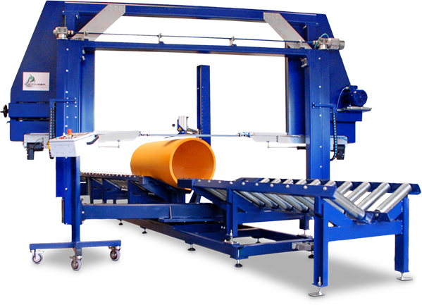
Conveying technology for special sawing machine
Delivery period: May 2015
The company Riexinger
The Eugen Riexinger GmbH & Co. KG is a globally operating mechanical engineering company based in Bad Liebenzell near Stuttgart in Baden-Württemberg. For more than 50 years it has been developing, producing and supplying equipment, plants and large-scale machines for processing all kinds of plastics.
By loading the video, you accept YouTube's privacy policy.
Learn more
Clients
Features
- Conveying Elements: Roller conveyor
- Convey Goods: Plastic pipes Ø 400 mm - 1200 mm
- Industry: Special mechanical engineering
The special sawing machine BSM 1200 / 1200 S-V
The BSM 1200 S-V (right) is used for sawing plastic pipes with a diameter of 400 – 1200 mm and a length of 3000 – 6000 mm. It allows angle cuts from 0 – 45 degrees. In the original basic version, the BSM 1200 is equipped with a simple V-table (left).

The challenge
Because the BSM 1200 is equipped with a simple V-table, the plastic pipe must be manually positioned and fixed for cutting.
Riexinger asked us to develop and implement a robust and cost effective solution, using a sketch designed by the company, in custom-made form, to increase the efficiency and throughput time of the machine saw.
The solution
The V-table was equipped with a v-shaped roller conveyor without drive and a chain conveyor placed in between including a driver. On the one hand, these technical modifications make it possible to automate the feed of the plastic pipe to be sawn. The incremental encoder installed on the motor allows the end position of the pipe to be precisely controlled. On the other hand, the v-shaped roller conveyor ensures that the plastic tube is centered on the elements. This ensures that the manually set cutting angle is maintained exactly at the end. A short film by our client Riexinger, which you can find above, illustrates how our solution works in practice.
Ergonomic storage rack
Ergonomic storage rack
Delivery period: August 2017
The client: DB Fahrzeuginstandhaltung GmbH, Werk Fulda
DB Fahrzeuginstandhaltung GmbH, headquartered in Frankfurt am Main, is a globally active company that offers maintenance services. Its customers include operating companies, leasing companies and manufacturers of rail vehicles and rail vehicle components. DB Fahrzeuginstandhaltung GmbH operates 12 locations in Germany. The Fulda plant specialises in the repair of brake components for all types of rail vehicles.
By loading the video, you accept Vimeo's privacy policy.
Learn more
Clients
Features
- Conveying Elements: Storage techniques
- Convey Goods: Brake components with max. 100 kg per basket
- Industry: Passenger and freight traffic / rail vehicles
The task
Production of a driven rotary system to be manually loaded with baskets, consisting of roller conveyors and rejectors.
The previous working principle at DB Fahrzeuginstandhaltung: The employees had to wait until the required basket with reusable old parts was transported to them – quasi like in a rolling sushi restaurant. As before, the spare parts required for repair were to be collected and transported from a separate spare parts warehouse on a project-specific basis.
Of course we could have implemented the wishes of our client 1:1. But: Such a rotary system already existed, but for several reasons, such as wear and tear of the components, it had not proven itself. After an on-site inspection by our project team, we were not satisfied with a mere retrofit or new construction of the system. And we put our heads together with those of DB Instandhaltung employees to develop a better solution together.


The solution
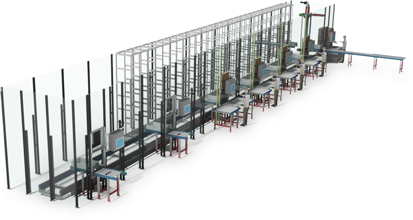
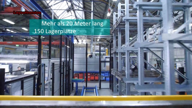
an assembly line with automated transport to and from several repair and testing stations and the installation of storage racks for old and spare parts baskets
Together we developed a solution with the following challenges: The new assembly line had to meet ergonomic requirements, improve the occupational safety of the employees, reduce the error rate and optimize process safety. The individual work steps of storage, merging of old and new spare parts that can be reused, transport to the repair site, intermediate storage, transport to the test site and storage / provision of the finished repaired brake component* were to be automated as far as possible.
The conveying process in detail
In advance, the used brake modules are dismantled and the old parts that can no longer be used are disposed of in an environmentally friendly manner. The reusable parts are cleaned in a washing plant. Now the new assembly line comes into play:
Storage of the still usable old parts
An individually marked basket with cleaned old parts is recorded by a member of staff in a computerised system at an entry point. He opens a transparent lifting gate and pushes the basket to a collection point. From there, the FlexShuttle transports the basket to the opposite storage rack, where spare parts are also stored.
Inspection of the repaired brake control
In principle, the same work steps are carried out here as for the repair itself. Only the work processes within the employee’s workplace are different. The system, which costs around 250,000 euros, is controlled by a network-compatible Siemes S7-1500 controller. The assembly line was connected to the internal DB in-house network by means of EDP technology so that the data of the conveyor system can be visualized web-based. We have to commission the new assembly line within the agreed period of two weeks without any problems and have it accepted by the customer.
Repair of the brake component
An employee requests the desired basket via a control panel. The FlexShuttle transports it to the staging area in front of the repair site. The employee pulls the basket through the lift gate to his workplace. He scans the basket and requests the basket containing the appropriate spare parts. This is transported and received in the same way as the old parts basket. The employee removes the spare parts and requests the return transport of the empty basket. He pushes it to the staging area, from where it is transported to the outfeed roller conveyor. From there the empty basket is picked up and taken to a central collection point. Afterwards the repair is carried out. Then the repaired brake component is transported by FlexShuttle from the staging area on the same route to the intermediate storage back to the opposite rack.
The customer benefit
- Higher process reliability:
Durch die EDV-technische Erfassung der gekennzeichneten Altteil- und Ersatzteilkörbe wurde die richtige Zuordnung und der Transport der für ein Projekt benötigten Teile zur Reparaturstelle automatisiert und die Fehlerquote minimiert. - Reduced risk of accidents:a
Employees at the repair site no longer have direct or manual access to the baskets, which were previously transported automatically. They pull the required baskets from a non-driven protection zone of the system to their workplace.
- Improved ergonomics:
It is no longer necessary to walk along paths to pick up the spare parts baskets, which are sometimes difficult to carry, and the work is much less physically demanding for the employees and therefore less stressful for their backs. - Bigger storage capacity:
Additional storage capacity was created and a buffer area for spare parts baskets was integrated